| Detector | Optics | FOV | Bandwidth (nm) |
Area (cm 2) | Resolution | Sensitivity (FUV) |
|||
| UV | Optical | Geometric | Effective | Angular | Time | ||||
| Ph. counting, CCD | CCD, Photometer | Twin Ritchie Chretian, 2 mirror system | 28' | 130 - 180 200 - 300 320 - 550 |
880 | FUV: ~12 NUV/Opt: ~50 |
1.8'' | 10 ms | 20 mV (5 σ) 200 s |
Overview
UVIT is primarily an imaging instrument. Images are made simultaneously in three channels: FUV (130-180 nm), NUV (200-300 nm), and VIS (320-550 nm), in a field ~ 28’ circle and with a spatial resolution (FWHM) < 1.8”. In each channel, a set of filters are available, in the filter-wheels, for selecting a band. In the two ultraviolet channels, gratings are provided for low resolution (~ 100) slitless spectroscopy. The focussing optics is configured as twin R-C telescopes, each with a primary with effective diameter of ~ 375 mm.
The overall structure is shown below. Those parts of the telescopes which define locations of the optical elements are mostly made of Invar36, and the other parts are made of Aluminium alloy. The two telescopes are mounted on a cone-like structure of Titanium, which is attached to central cylinder of the S/C.
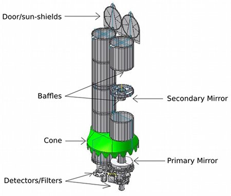
A cylindrical baffle extends over each of the telescopes for attenuating the radiation from off-axis sources. With these baffles the light reaching the detector from sources at 45 deg. from the axis is attenuated by a factor 109; with such an attenuation the light reaching the detector from full Moon at 45 deg from the axis is less than the average sky background. In addition to these baffles, the doors act as sun shades as long as Sun is at > 45 deg from the axis.
In order to avoid contamination of the optics due to ultraviolet assisted reactions, bright-earth-limb is kept away from the axis by >12 deg., and the sun is kept behind the sun-shield at all times even if UVIT is not observing.
The geo-coronal lines are very strong in day time, and a significant amount of solar radiation could be scattered by the other instrument son S/C into the baffles. Therefore, the nominal observation period is restricted to the night time ( In special cases, observations in day time could be considered).
The intensified CMOS detectors can either be used in a high gain photon counting mode, or in a low gain integration mode (in which signal in a pixel of the CMOS detector could be contributed by multiple photons).
Pointing accuracy of the S/C is ~ 3’, and for any pointing the aspect could drift by several tens of arcsec, at rates < 0.2”/s. In order to eliminate effect of this drift on the PSF, multiple short exposures (< 1 s each) are taken and are combined using shift and add. As the VIS field has adequate number of bright sources, images (taken in integration mode) from this channel are used to estimate the drift as a function of time.
There are three main contributors to the PSF: optics, detector, and drift of the aspect. Of these three the largest contribution is made by the detector and it is ~ 1” FWHM. The estimated overall FWHM, including the contributions of the optics and the drift, is 1.5”.
The peak effective area, excluding the losses in filters used for band-selection, is: ~ 20 sq cm for the FUV, and ~ 50 sq cm for NUV&VIS. An exposure calculator is available to estimate the expected signal levels for point sources observed through the various filters. In addition, a simulator is available which can generate the output image expected from an observation with UVIT, for an extended source with known distribution of the intensity.